%201.png?width=146&height=103&name=Slice%203%20(72)%201.png "JV Logo")

Even the best-designed tools can fail without close attention. When stamping operations run smoothly, it’s easy to overlook the subtle warning signs that indicate trouble ahead. But tool and die failure can grind production to a halt, leading to missed deadlines, rejected parts, and costly emergency repairs.
In this guide, we’ll walk through the leading causes of tool failure, how to spot the warning signs before they escalate, and proven strategies to extend tool life while maintaining precision.
Why Tool & Die Failure Often Go Unnoticed
Tool and die failure don’t happen overnight. One misaligned guide pin or a single burr can turn a high-precision operation into a costly delay. Most failures stem from a combination of factors:
- Material mismatches
- Process drift
- Environmental conditions
- Overlooked maintenance issues
- Design flaws
- Worn components
These failures occur when stamping or cutting tools lose functionality due to wear, misalignment, or damage. The key is recognizing that multiple factors often work together to create the perfect storm for failure.
1. Material Tolerances
Using material with incorrect tolerances, such as the wrong thickness or width, is one of the fastest ways to destroy tooling. For instance, a die design for thin aluminum sheet could fail prematurely if used on thicker carbon steel. The mismatch creates excessive stress, accelerating wear and leading to defects like burrs, warping, or incomplete forming.
When material dimensions are out of tolerances (too thick/wide or thin/narrow), or if there are structural characteristics like material camber (a form of material inconsistency or deformation), it can lead to misfeeds during the stamping process, resulting in unneeded costs and downtime.
|
Warning Signs of Material and/or thickness mismatch:
|
Diagnostic Tip: Always verify material specifications against die design tolerances before starting production.
Materials with high tensile strength like high-strength steel, superalloys, or titanium require more force and cause faster tool wear, while improper grain direction increases the risk of cracking and distortion.
To proactively prevent these issues and ensure consistent quality, it’s essential to have a reliable material supplier. By matching material properties to tooling capabilities from the start, you can prevent the most common cause of premature die failure. This foundation sets the stage for understanding how material characteristics interact with your stamping process.
2. Damage From Abrasive Materials
Harder, more abrasive materials cause accelerated wear on cutting edges and forming structures. This type of wear often goes unnoticed until quality starts declining significantly. The challenge lies in the gradual nature of abrasive wear, where each stamping cycle removes microscopic amounts of tooling material.
Abrasive wear manifests itself differently depending on the material being stamped.
|
Signs of Abrasive Material Damage:
|
Hardened steel creates a grinding action that dulls cutting edges. Certain alloys can cause galling where material transfers to the die surface. Piercing operations suffer particularly from this type of wear, especially when working with thicker, more challenging materials.
Prevention Tip: Use wear-resistant, hardened tool steel or carbide for forming challenging materials. For high-wear applications, machinists can also extend the lifespan of the die by applying protective coatings.
Implementing proper lubrication with the right type of oil and application method is essential. Effective lubrication reduces prediction, prevents material from sticking to dies, extends tool life, and minimizes heat generations.
Various types of lubricants, including mineral and synthetic oils, greases, solid lubricants (like graphite and molybdenum disulfide), penetrating lubricants, dry lubricants (like PTFE), and bio-based lubricants, are available to suit different operational conditions and material compatibilities.
Recognizing abrasive wear early allows you to add protective measures before damage becomes irreversible. While material properties set the foundation, it’s important to remember the stamping process itself creates the next layer of potential failure points.
3. Process Parameters That Drift off Course
Small changes in press speed, force, or lubrication can compound into major problems. For example, excessive speed can generate heat buildup leading to warping or material deformation. Conversely, insufficient force may cause incomplete part formation, while too much force stresses both tools and materials beyond their design limits.
Deviations in these critical parameters are often overlooked warning signs of potential tool wear or material resistance that could lead to failure if not addressed.
|
Critical process factors:
|
To proactively manage these factors and ensure consistent product quality, a comprehensive quality (QA) assurance process is essential. This includes adhering to internationally recognized standards such as ISO 9001:2015, which provinces a structured framework for establishing a consistent and high quality production process.
In order to maintain quality consistency in your process, use a diagnostic approach. Start identifying inefficiencies by conducting internal audits and utilizing other inspection techniques. This helps set clear guidelines for quality objectives, and provides a quality assurance framework that can be updated alongside your processes.
Diagnostic approach: Use real-time monitoring systems to track subtle parameter changes. Statistical process control (SPC) helps identify concerning trends before they become costly failures.
Maintaining tight control over process parameters creates a stable foundation for tool longevity. However, even with perfect process control, mechanical components will eventually wear and require attention.
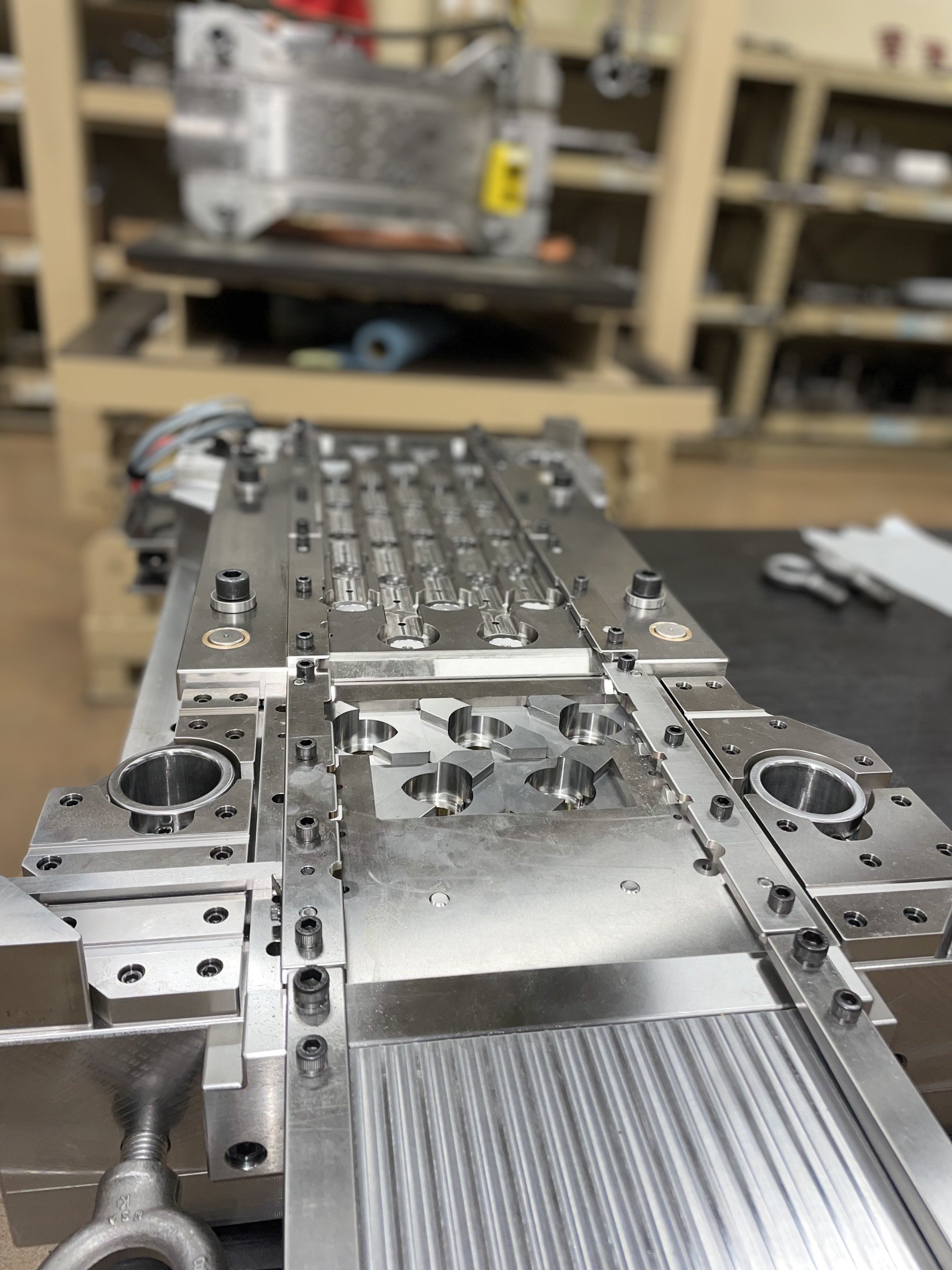
4. Misalignment With Worn Guide Components
Guide pins, bushings, and ball cages wear gradually from repetitive high-pressure operations. Even slight misalignments prevents stations from operating smoothly, causing uneven wear and dimensional inconsistencies. The subtle nature of alignment problems means they often develop slowly, making them easy to overlook until significant damage occurs.
Misalignment creates a domino effect throughout the entire die system. When one station operates slightly off-center, it places more stress on adjacent stations and can cause premature wear up and down the line.
Guide component degradation typically results from the constant high-pressure cycling inherent in stamping operations. However, die crashes or improper installation can accelerate the process dramatically.
|
Warning signs of misalignment:
|
Diagnostic Tip: Check guide components during routine inspections. Look for wear patterns that indicate developing misalignment issues. Proper shim application maintains positional accuracy and prevents uneven wear distribution.
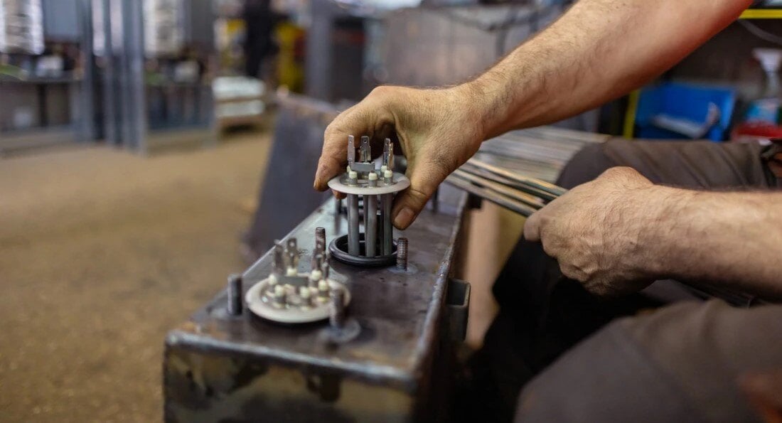
Address alignment issues proactively by implementing milestone preventive maintenance (PM) schedules to replace long-term wear components, such as guide pins, guide bushings, and ball cages, before they degrade significantly.
Establishing a schedule for routine inspections, lubrication, sharpening, cleaning, and component wear will help prevent cascading failures throughout your tooling system. While mechanical wear is inevitable, poor initial design can cause faster wear in a short period of time.
5. Design Flaws That Create Stress Points
Overly tight tolerances, inadequate bend radii, or improper hole spacing create stress concentrations that lead to premature failure. Design-related failure indicators to look out for include:
|
Design-related failure indicators:
|
Prevention Tip: Use design for manufacturability (DFM) principles from the project’s start. Use 3D simulation software to identify potential issues before creating expensive physical prototypes.
Investing in proper design analysis up-front can help prevent costless hours of troubleshooting later.
6. Environmental Factors
The manufacturing environment plays a more significant role than many realize. Temperature swings of just a few degrees can cause materials to expand and contract, affecting tolerance stability. Humidity impacts lubrication effectiveness and can accelerate corrosion. Workspace contamination from particles and debris damages tooling and creates surface defects.
These environmental factors often work silently in the background, gradually degrading tool performance without obvious immediate symptoms.
|
Environmental warning signs:
|
To stabilize temperature and humidity levels, maintain a controlled environment throughout the production processes. Regularly monitor the workplace environment for temperature metrics, contamination sources, and workspace cleaning procedures to help maintain constant production conditions.
7. Maintenance Shortcuts That Cost More Later
Skipping regular tool maintenance is a risky and expensive shortcut in the long run. Dull cutting edges compromise quality and increase cycle times unnecessarily. Infrequent inspections miss subsurface flaws that could be addressed before they cause catastrophic failures.
Poorly maintained tools and dies lead to decreased precision and consistency of output, resulting in lower-quality products that do not meet standards or specifications.
|
Maintenance-Related Failures:
|
To counter these risks, use a proactive approach by establishing a structured maintenance program with schedules for routine maintenance. Utilizing advanced technologies such as vibration analysis, thermal imaging, or ultrasonic testing techniques, predictive maintenance helps detect subtle abnormalities that could indicate a malfunction before failures occur.
This proactive diagnostic approach helps minimize unexpected breakdowns and costly downtime. Documenting all maintenance activities thoroughly is also important for tracking tool performance patterns over time.
Consistent maintenance practices tie together all other die failure prevention strategies, creating a comprehensive approach to tool longevity. This systematic foundation enables more efficient failure diagnosis when problems do occur.
How to Diagnose Tool & Die Failure the Right Way
Accurately pinpointing the root causes of issues requires a mix of systematic approaches.
- Use simulation data: Compare actual performance against 3D modeling predictions to identify where reality diverges from design intent.
- Monitor real-time metrics: Track production data continuously for subtle anomalies that indicate developing problems.
- Employ advanced inspection: use coordinate measuring machines (CMMs), ultrasonic testing, and detailed visual inspections to catch issues early.
- Document everything: Keep detailed records of tool performance, maintenance activities, and failures to identify recurring patterns.
- Find root causes: Remember that one minor misalignment or measurement error can cascade into complete die failure. Small details matter tremendously in precision manufacturing operations.
Tool and die failure isn't just about noticing worn edges or broken components; it’s also about developing process awareness and implementing proactive prevention strategies.
By understanding these common causes and the right way to troubleshoot, manufacturers can extend tool life, maintain dimensional accuracy, and avoid costly production disruptions.
Ready to Level up Your Manufacturing Game?

For expert maintenance solutions tailored to your needs Contact us today.
Tool and Die Repair Maintenance
Machining Vs. Casting: Key Differences, Advantages, & Applications