%201.png?width=146&height=103&name=Slice%203%20(72)%201.png "JV Logo")

How Many Design Iterations Does It Take to Get Your Product Right?
For most engineering teams, the answer is frustratingly high. Each prototype cycle consumes lead time, budget, and momentum toward launch—while pressure increases to iterate faster and learn more from every build.
That’s where CNC machining prototyping changes the equation. Unlike 3D printing or manual methods, CNC prototypes can be produced in production-grade materials with real-world accuracy, so you can validate function, fit, and performance with fewer surprises when you scale.
In this guide, you’ll learn how the CNC prototyping process works from CAD file to finished part and the process disciplines that help teams prototype faster, test smarter, and transition confidently into production.
The CNC Prototyping Workflow: From Design to Delivery
Understanding the end-to-end workflow helps you see where to optimize for speed and where to invest in precision. Below is a practical, shop-reality view of the CNC machining prototyping process.
1. CAD Designs & DFM Optimization
Your prototype journey begins in CAD—whether you’re using Fusion 360, SolidWorks, or another platform. But one of the most common causes of prototype delays is designing without manufacturability in mind.
Design for Manufacturability (DFM) is not a checkbox. It is the process of aligning design intent with how parts are actually machined. This way, you reduce setups, cycle time, rework risk, and inspection burden.
Key DFM principles for faster CNC machining prototypes:
- Minimize part flips and setups: Every reposition adds setup time and introduces alignment risk.
- Avoid unnecessarily tight tolerances: Every additional 0.001” tightens inspection requirements and may require specialized tooling or processes.
- Design with tool access in mind: Deep pockets, sharp internal corners, and complex undercuts can multiply machining time.
- Prefer standard tooling and features: Nonstandard radii, uncommon drill sizes, and custom cutters increase lead time and cost.
DFM is also the point where you should decide what “prototype-ready” means for your project:
- Which dimensions are function-critical?
- Which features can be simplified for learning speed?
- Which requirements must be met now to avoid rework later when scaling?
| A focused DFM review early can eliminate hours of machining time and prevent costly iteration cycles. |
2. CAM Programming & Material Selection
Once the design is optimized, the next step is translating the 3D model into machine instructions using CAM software. CAM programming defines the toolpaths your CNC machine will follow and includes decisions such as:
- Cutting tools required (end mills, drills, boring tools, etc.)
- Feed rates and spindle speeds
- Roughing vs. finishing strategies
- Approach angles, depths of cut, stepovers, and stepdowns
Material selection is a prototyping decision—not just a purchasing decision
Material affects machining time, cost, and the validity of functional testing. If your goal is to validate how the part behaves in service (load, wear, thermal performance, assembly), prototyping in the real-use material reduces false confidence and downstream surprises.
Common prototyping materials and their trade-offs:
|
Material |
Machining Speed |
Cost |
Best For |
|
Aluminum 6061 |
Fast |
Low-Moderate |
General prototyping, proof of concept |
|
Aluminum 7075 |
Moderate |
Moderate |
High-strength applications (Ex. aerospace) |
|
Tool Steels (D2, A2, O1) |
Slow |
Moderate-High |
Stamping dies, wear-resistant components |
|
Stainless Steel 303/304 |
Moderate |
Moderate |
Corrosion resistance, medical devices |
|
Brass |
Fast |
Moderate |
Electrical components, bearings |
|
Carbide |
Very Slow |
High |
Extreme wear resistance, specialized tooling |
At JV Manufacturing, we frequently prototype in tool steels, aluminum alloys, and carbide because these materials mirror what our customers will use in production. Testing with the actual material eliminates the guesswork about how your design will perform under real-world conditions.
If you anticipate production constraints (volume, surface finish requirements, heat treat steps, coating specifications), align material selection and process routing early so your prototype data remains valid.
3. Machining & Setup Efficiency
With CAM complete and material selected, machining begins. The typical CNC prototyping sequence looks like this:
- Secure stock material with proper workholding to prevent vibration and maintain accuracy.
- Load tooling into the machine’s tool changer.
- Upload G-code generated by CAM.
- Run the first operation with real-time monitoring for tool wear, chatter, or program issues.
- Perform secondary operations such as part flips, additional faces, or feature completion.
Where prototypes win or lose time: setups, not cutting
Much of the prototype lead time is driven by how many times a part must be touched, indicated, re-fixtured, and re-qualified. Efficient prototypes are built around process consolidation:
Time-saving strategies:
- Consolidate prototypes and variants into one machining session when possible
- Design fixtures that enable multiple parts per setup
- Group operations to reduce tool changes
- Reduce part flips through thoughtful fixturing and (when appropriate) 5-axis machining
Tool wear monitoring also matters even in prototyping. As tools degrade, dimensions drift, especially across multiple parts or multiple variants, creating false signals in your testing.
4. Finishing, Stress Relief, and Inspection
Your part may come off the machine “complete,” but it is not necessarily ready for testing. Finishing and inspection are the gates that determine whether your prototype teaches you something reliable or sends you chasing noise.
Common finishing operations
- Deburring (remove sharp edges and burrs)
- Surface treatments (sanding, bead blasting, polishing)
- Anodizing or coating (when surface properties matter)
- Heat treat and stress relief (when required for performance or stability)
Heat treat and internal stress: why it matters in CNC prototyping
CNC milling and turning can introduce residual stresses—especially when removing large volumes of material, machining thin walls, or roughing aggressively. Those stresses can show up as:
- warping or distortion during machining
- movement after unclamping
- dimensional drift over time
- or problems in downstream steps (assembly, coating, grinding, EDM, or additional machining)
If your part is a tool steel, a high-strength alloy, or anything where hardness and stability are part of the functional requirement, heat treat may not be optional—it may be part of the process definition.
Practical guidelines for prototype planning:
- Decide early if heat treatment is required for functional testing (hardness, wear, fatigue, load).
- Plan machining allowance if heat treat will occur before final sizing—distortion is normal, so leave stock for post-HT finishing passes.
- Validate hardness and critical dimensions after heat treatment as part of your prototype inspection plan.
- When stability matters (tight flatness, thin-wall geometry), consider stress relief between roughing and finishing to improve repeatability.
Inspection validates learning
Inspection is not simply “did we hit the print.” It is how you confirm that prototype test outcomes are tied to design intent, not uncontrolled variation.
Common inspection tools include:
- Calipers and micrometers
- CMM (Coordinate Measuring Machine)
- Optical comparators
- Surface roughness testers
Prototype inspection data is also how you refine production drawings. If a feature repeatedly sits at the edge of tolerance, you can adjust geometry, process plan, or tolerance definition before committing to production tooling.
Best Practices to Prototype Faster and Learn More
Speed matters in prototyping, but only if each iteration generates actionable insights. These best practices help you maximize both velocity and learning.
Simplify Design to Speed Machining & Reduce Costs
Every feature you add to a part increases the machining complexity. The question to ask isn’t “Can we make this?” but rather “Does this feature teach us something we need to know?”
Simplification strategies that maintain functional value:
- Remove non-essential aesthetic features and save refinements for later iterations.
- Loosen tolerances where possible: If a dimension doesn’t impact function, opening it from 0.001” to 0.005” can slash machining time.
- Avoid deep cavities or complex undercuts that require specialized tooling to dramatically increase cycle time.
- Use standard hole sizes rather than custom-reamed holes for faster machining.
- Minimize thin walls: Features under 0.030” thick are fragile, difficult to machine, and slow to produce.
The goal is to preserve the functional characteristics you need to test while eliminating everything that adds time without adding insight.
Be Smart about Batch Prototypes
If you need multiple prototypes, whether for testing design variants or for distributing to stakeholders, smart batching can reduce per-part costs by 40%-60%.
Batching benefits beyond cost:
- Setup time is amortized across multiple parts
- Tool paths are optimized once and executed repeatedly
- Consistency across the batch improves comparison testing
- Faster turnaround when you need multiple units
The key is planning. If you suspect iterations or variants are coming, communicate early so fixturing and programming can accommodate change efficiently.
Use Real-Use Materials and Inspect Early
Here’s where CNC prototyping delivers its most significant advantage over additive manufacturing: you can test in the actual material your production parts will use.
This matters more than most engineers initially realize. Material choice affects:
- thermal behavior
- strength and fatigue
- friction and wear
- surface finish and mating behavior in assemblies
Testing with the right materials reveals failures and performance issues that plastic prototypes simply cannot show. A prototype in aluminum or tool steel experiences the same stresses, temperatures, and wear patterns your production parts will face.
Early inspection accelerates learning. Don’t wait until your design is “final” to measure parts carefully. Dimensional data from early prototypes helps you understand:
- Which tolerances are practical
- Which features risk falling out of spec
- How machining parameters affect finish and geometry
This early feedback loop prevents you from over-specifying tolerances on production drawings or under-specifying features that actually need tighter control.
Design the Prototyping Process to Scale (No Shortcuts, Full Quality Discipline)
Prototypes often fail to translate into production because the prototype route relied on one-off heroics—extra handwork, special setups, or skipped quality gates. If you want prototypes that accelerate production readiness, build the process with scale in mind:
- Run the complete process deliberately: define a route, complete each operation in sequence, and include in-process and final checks—not just “make it work.”
- Avoid non-scalable touch labor: reduce, eliminate, or automate preparation steps (setup, deburring, manual blending) and post-processing where possible.
- Prototype with production intent: choose feature strategies, tooling approaches, and inspection methods that can be repeated at higher volumes.
- Create repeatable process documentation early: programs, setup sheets, inspection plans, and revision control reduce friction when volume increases.
This approach keeps prototypes fast while ensuring they remain credible indicators of production performance.
Integrate Virtual Prototyping
Physical prototyping and virtual simulation aren’t either-or propositions. The most effective product development teams use both strategically.
Virtual prototyping, using finite element analysis (FEA), computational fluid dynamics (CFD), or other simulation tools, allows you to test extreme conditions, failure modes, and parameter variations that would be expensive or impossible to recreate physically.
The integration strategy that works:
- Use virtual prototyping to eliminate flawed concepts
- Build CNC prototypes to validate simulation assumptions and material behavior
- Use physical test data to calibrate your virtual models
- Use simulations for minor variations; build physical prototypes for major design changes
This approach reduces the total number of physical iterations while increasing confidence in each one you do build.
Common Pitfalls in CNC prototyping
Even experienced engineering teams make mistakes that slow down prototyping cycles. Here are the most common and most avoidable pitfalls.
Over-Engineering the First Prototype
The first prototype exists to answer questions, not to be perfect. Teams that try to incorporate every feature and every finish detail in iteration one end up with expensive prototypes that take weeks to produce.
Better approach: Build the minimum viable prototype that tests your core assumptions. Add complexity in later iterations once you’ve validated the fundamentals.
Ignoring Your Machinist’s Input
Your machining partner has seen thousands of parts and knows what works and what doesn’t. Engaging them early in the design phase, ideally during CAD development, prevents costly redesigns later.
Ask questions like:
- What would make this easier to machine?
- Are these tolerances realistic for this geometry?
- Could we achieve the same function with a simpler feature?
This collaboration often reveals simpler, cheaper approaches you might not have considered.
Treating Prototypes Like Production Parts
Prototypes serve a different purpose than production parts. They need to be functional and accurate on critical features, but they don’t need production-ready finishing, packaging, or documentation.
It is essential to clarify with your machining partner which features are critical for testing and which can be left rough. This distinction can cut lead times significantly.
Not Planning for Iteration
If you only budget time and resources for one prototype, you’re almost guaranteed to need a second one. Build iteration time into your project schedule from start to finish.
Realistic prototyping timelines typically include:
- Initial prototype: 2-3 weeks
- Testing and evaluation: 1-2 weeks
- Design revision: 3-5 days
- Second prototyping: 1-2 weeks (faster because of lessons learned)
- Validation testing: 1 week
These avoidable mistakes highlight the central truth of efficient CNC prototyping: it's a process of learning, collaboration, and strategic simplification, not immediate perfection.
CNC Prototyping vs. Other Prototyping Methods
CNC machining isn’t the only way to build prototypes, but it offers distinct advantages that make it the preferred choice for functional testing and pre-production validation.
| Category | CNC Machining |
3D printing |
Manual Machining |
|
Best For |
Functional testing and pre-production validation |
Design visualization, form studies, and complex geometry prototypes |
One-off prototype and quick concept testing |
|
Material Capability |
Uses production-representative metals and plastics |
Limited to printable materials (resins, polymers, composites) |
Broad, but depends on machinist's skill |
|
Geometric Complexity |
High, but limited by tooling access |
Extremely high; can produce shapes impossible to machine |
Moderate; limited by human precision |
|
Repeatability & Precision |
Excellent dimensional accuracy and repeatability |
Moderate; varies by printer quality |
Low to moderate; not repeatable without extensive skill |
|
Surface Finish Quality |
Superior finish and tight tolerances |
Often requires post-processing |
Depends on manual skill and tools |
|
Durability & Load Testing |
Ideal for real-world functional testing |
Poor for structural or load-bearing parts |
Good for functional parts, but inconsistent |
|
Speed of Production |
Moderate; setup times required |
Very fast for single parts |
Slow; entirely manual process |
|
Scalability/ Iteration |
Easily repeatable via CAM and G-code documentation |
Limited scalability; each print is a separate run |
Difficult to reproduce or scale |
|
Documentation & Process Control |
Digital files create a reproducible, programmable workflow |
Model files are reproducible, but less process-controlled |
No formal documentation; depends on the machinist |
CNC Machining bridges the gap between design visualization and production readiness. While 3D printing excels in speed and complexity for early prototypes, CNC prototyping provides the material accuracy, strength, and surface quality necessary for true functional validation, which neither 3D printing nor manual machining can fully replicate.
When to Move from Prototyping to Production
The transition from prototype to production represents a critical decision point. Move too early, and you risk expensive tooling for a not-quite-right design. Move too late, and you miss market windows and competitive opportunities.
Here are some signs that you’re ready for production:
- Design validation complete: Testing confirms the design meets all functional requirements.
- Material selection finalized: You’ve tested the actual production material and confirmed performance.
- Tolerances rationalized: Your specifications reflect what’s truly needed, not theoretical ideas.
- Clear volume requirements: You understand production quantities and rate requirements.
- Validated cost targets: Prototype costs have informed realistic production cost projections.
At this stage, progressive die manufacturing or other high-volume processes become appropriate. But the insights gained through CNC prototyping directly inform the design of production tooling, reducing risk and accelerating the ramp-up to full production.
Ready to Accelerate Your Product Development?
CNC machining prototypes deliver speed, accuracy, and real-world insights that accelerate product development and reduce risk. By understanding the complete workflow, from CAD optimization through machining, finishing, and inspection, you can make strategic decisions that maximize learning while minimizing time and cost.
Each prototype should teach you something new about your design, your material, or your manufacturing process. When you elevate your understanding of CNC prototyping, you transform it from a simple fabrication step into a strategic tool for innovation.
Are you prepared to accelerate your product development through precision CNC prototyping? JV Manufacturing combines advanced machining capabilities with engineering expertise to help you prototype faster and learn more from every iteration.
Contact our team today to discuss your prototyping needs and discover how we can help you move from concept to production with confidence.

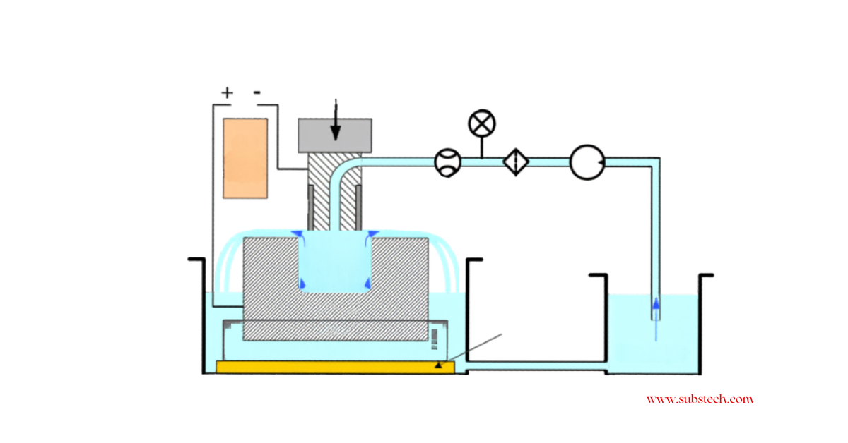
Understanding The Electrochemical Machining Process
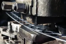
Reducing Manufacturing Lead Time with Progressive Die Stamping